
Activated Sludge Primer Need to know more? Send us an email or feel free to search our online series with our give away search engine: |
Conventional Activated Sludge Process: Activated sludge process utilizing plug-flow through the aeration basin with primary effluent and [return] activated sludge (RAS) fed at the head end and uniform aeration throughout.
Complete Mix System: Idealized continuous flow reactor in which fluid particles are immediately dispersed throughout the reactor. Homogenous wastewater reactor contents.
Plug Flow: Idealized continuous flow reactor in which fluid particles are subjected to uniform conditions, e.g. mixing energy and detention time, in any given cross section, and are discharged in the same order in which they entered.
Step Feed System: wastewater is added at several points along the length of the aeration basin rather than just at the basin's head end.
Tapered Aeration: activated sludge process variant in which the amount of air added varies along the aeration basin with a maximum at the head end and a minimum at the outlet end.
Contact Stabilization Process: a modification of the activated sludge process in which wastewater is aerated with a high concentration of activated sludge for a short period, usually less than 60 minutes, to obtain BOD removal. The solids are subsequently separated by sedimentation and transferred to a stabilization tank where aeration is continued, starving the activated sludge before returning into the aeration basin.
Extended Aeration: a modification of the activated sludge process utilizing very long aeration periods and low food-to-microorganism F/M ratios, enhancing endogenous respiration, i.e. utilization of internal cellular material as food under aerobic conditions when an adequate external food supply is unavailable, (thinning up if you want).
Broadly speaking, aeration systems employed in activated sludge plants are popularly classified as either surface aeration systems or submerged type aeration systems.
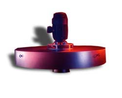
Typical examples of surface aeration systems include most frequently floating or pier-anchored mechanical type units, such as direct-drive, high speed units or gear driven, low speed units. Flow can be either upflow or downflow and either axial or radial/centrifugal.
A typical direct-drive, high speed unit consists of a motor, a fiberglass or stainless steel float and an intake/suction cone. The most common designs can be marine type impellers assisted with fixed/non-rotating diffusion heads or screw centrifugal, Archimedes type impellers. A good quality, high speed unit can and should deliver say about 2.4 lbs O2/hp/hr, +/-10%, in clean water.
A typical gear-driven, low speed unit consists of an electric motor, gearbox, relatively large diameter rotors (say up to 10' or 3.2m), spool and mounting plate for pier-mounted units Floating type low speed units include knocked-down, float platforms that can be easily assembled onsite. A good quality, low speed unit can and should deliver say about 3.5 lbs O2/hp/hr in clean water. .
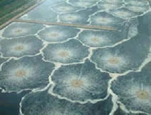
Surface aerators are typically employed in the relatively shallower ponds, basins or tanks.
The most popular submerged type aeration systems include diffused aeration systems and submerged, turbine-type aeration and mixing aerator configurations.
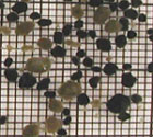
Diffused aeration systems are frequently classified into two major categories according to the diffuser's pore/bubble size, i.e. fine-pore diffusers and medium/coarse diffusers.
Medium/coarse diffused aeration systems are used in foul-prone applications.
Submerged, turbine-type aeration systems include slow rotating bottom impellers coupled with grade level blowers. The submerged impeller draws liquid from the bottom for reactor mixing and effects oxygen transfer/bubble shearing Blower units provide air to the submerged turbine assemblies, (e.g. 35-40 SCFM per turbine share motor HP, ballpark 50/50 total HP split between blower and submerged turbine) via flexible hoses as needed to satisfy specific operating modes/targets, e.g. just mixing (off) , anoxic stage, SBR phases, filamentous bacteria control.
Aspiration type units provide good oxygen transfer but also cause a circular pattern of flow through the reactor. This circulation pattern is OK if the basin type requires circulation, such as oxidation ditches and facultative lagoons, but BNR reactors do not need this circulation. Aspiration type aeration devices also provide a high velocity jet that can cause erosion of the bottom or sides of the basin if the basin has a shallow depth or the unit is too close to the side of the berm.
Most types and brands are suitable for AS applications, but each has its own best applications. For example, brush aerators are best for oxidation ditches while fixed diffusers and surface aerators are best for conventional AS systems. The key is to size the unit properly for each application. Once OTR characteristics are established, the sizing is fairly straightforward. Other factors include alpha factor, impact of floc size and settleability, impact on effluent TSS, etc. The key phrase is "if properly sized/selected."
Solids can separated by sedimentation or floatation or membranes and transferred back to the aeration basin. Some of the clarifier underflow is returned to maintain the desired biomass inventory level and excess is wasted as WAS (waste activated sludge). Typical embodiments include bottom scrapers and highly efficient tapered suction header designs.
The following approach can be used to estimate oxygen requirements
Ro = (1 - b * Yg ) * Rs + b * d * X , mg
O2/L-hr
where:
Rs = rate of COD conversion, mg COD/L-hr (usually COD load * removal
efficiency),
Ro = rate of oxygen uptake, mg/L-hr,
X = microorganism concentration, mgVSS/L
Yg = biomass yield coefficient, mass VSS/mg COD removed (usually 0.3 kg
VSS/kg COD removed)
b = 1.42
d = endogenous decay rate (usually 0.1/day)
So for 42 mg COD/L-hr maximum COD loading
rate ( = 1 g COD/L-d) and an assumed 2,000 mg/L VSS in the mixed liquor
and an endogenous decay rate of 0.00417/hr (= 0.1/day), the oxygen uptake
rate would be:
Ro = (1 - 1.42*0.3) * (42 * 90%) + 1.42 * 0.00417 * 2000 mg/L = 34 mg
O2/L/hr
The aeration equipment would have to equal or
exceed this rate to insure positive DO in the aeration basin. Of course,
you will need to make sure you calculate the loading rates correctly in
the zone of interest. For example, for plug flow type processes, the COD
loading rate would be that in the first section of the basin.
Most manufacturers and equipment vendors have
readily available software for preliminary designs and will generally
assist you with proper equipment/unit selection including
recommended/minimum/maximum depth, oxygen dispersion diameter, complete
mix diameter and so on.
Adequate contact must be provided between organic wastewater constituents and the microorganisms.
Aerator manufacturers often provide sizing charts or layout guidelines including recommended water depth, oxygen dispersion diameter and complete mix diameter estimates, the following being sample formulas for low-speed,
floating surface mechanical aerators:
Mixing diameter (feet)
= 2 x (( 646 x H.P.)/DEPTH)^0.5
Oxygen dispersion diameter (feet) = 2 x ((6490 x H.P.)/DEPTH)^0.5
One surface aerator manufacturer's rule of thumb suggests that the HP/mg power density required for mixing with up-draft, direct-drive aerators is up to 1 HP/1,000 ft3 or about 133 HP/mg.
Rightly or wrongly, AOR/SOR ratios of about 0.7 are frequently
used for quoting or budgeting direct-drive, surface mechanical aerators.
However, until alpha, beta, theta, elevation and required residual D.O.
are known the 0.7 factor is nothing but a glorified guess. It should be
obvious you don't want this type of guessing especially in the light of
present day availability of highly qualified treatability assessments.
It's illustrative to see how each aerator manufacturer decides to
showcase their units. The following argumentation was proffered by a
manufacturer of both surface aerators and submersible aerator blower
combinations:
"Based on a flow rate of 1200 m3/day and a BOD of 1043 mg/l and
TKN of 11 mg/l we calculate that the AOR will be 4385 lbO2/day. Using a
correction factor to SOR = 8570 lbO2/day = 357 lbO2/hour.
With our surface floating mechanical aerators at a transfer efficiency of
2.5 lb/Hp/hour you will need 142.8 BHp. Due to the shallow basin [swd=3.5m]
we recommend three (3) 50 Hp (37.3 kW) aerators of stainless steel float
design.
If you can change your basin size to 16.5m square by 6.1m liquid depth
then we would recommend one (1) 30 Hp submersible aerator mixer supplied
air from one (1) 75 Hp blower with accessories. Total energy draw will be
30HP for the submersible aerator mixer and 64HP for the blower for a total
of about 94 Hp (70 kW).
The submersible aerator mixer can either be hydraulic driven or electric
driven at the same cost. The submersible aerator mixer and blower
combination should save over 40 Kw of energy costs and this should more
than pay for the capital cost difference in less than two years."
We have done a number of tests with refinery WW, all aerobic which is almost universal. While most hydrocarbons can be degraded aerobically, excursions in load can challenge the capacity of the microorganisms to keep up with consequent high VOCs in the effluents. In the US, most refineries have to cover the aeration basins or use high-purity oxygen systems to reduce release of volatile organics.
For the purpose of rough calculations we can, whatever the units used, and using say COD as constituent, combine these two formulas:
Yn = Yo * ( 1 + 0.2 * Kd * SRT) / ( 1 + 1.2 * Kd * SRT)
Yn = bugs in tank * 100 / ( SRT * kgCOD/day * COD removal points)
Thus we have
bugs in tank * 100 / ( SRT * kgCOD/day * COD removal points) = Yo * ( 1 + 0.2 * Kd * SRT) / ( 1 + 1.2 * Kd * SRT)
Solving for one of the SRT we get the coveted iteration formula:
SRT = bugs in tank * 100 * ( 1 + 1.2 * Kd * SRT) / ( kgCOD/day * COD removal points * Yo * ( 1 + 0.2 * Kd * SRT) )
From now on it's just a matter of allowing Excel to perform circular reference iterations (you may have to enable this setting in your Excel version).
For those unfamiliar with iterative methods (a numerical analysis classic) one way to find a root of an equation is to solve for the variable and give iterative methods a try.
Were we to find a root for say
a * x^2 + b * x = (a * x + b) * x = 0
One possible iteration formula to try could be solving for x as follows:
x = 1 / (a * x + b)
While it may seem laughable to do it for this case the truth is that it works great for the not so immediate cases. With minor tweaks it can be used for UASBs, HAFs, BVFs, BNR TFs of all sorts.
It is not wise to use air stripping for nitrogen removal. Aerobic nitrification/denitrification is much more economical. Some possible treatment train may be as follows:
1. Anoxic/aerobic nitrification/denitrification in tanks-in-series arrangement (ie. AO2, Bardenpho, UCT, etc.)
2. Alum precipitation in an independent flocculation-clarifier from the aerobic process to remove phosphorus and to precipitate suspended solids (This separate clarifier avoids adding chemicals directly to the aeration system). Some powdered activated carbon may have to be added to remove color and soluble organics if color and additional COD removal is required.
3. Granular media filtration for final suspended solids removal
4. disinfection as needed.