
Aerated Lagoons Primer Need to know more? Send us an email or feel free to search our online series with our give away search engine: |
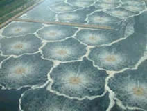
Aerated lagoons come in basically two flavors, i.e. complete mix type systems and partial mix systems.
Complete mix (CM) systems are designed to insure thorough content mixing and maintain lagoon solids in suspension. Typical power levels hover about 100 HP/mg. Aerated lagoons of this type are basically activated sludge plants with no sludge return. Either a subsequent cell or a partitioned zone separated by baffles is used for settling.
Partial mix (PM) systems only aim to insure uniform dissolved oxygen throughout the reactor and mixing is partial, allowing a portion of solids and particulate BOD/other to settle and anaerobically decompose at the bottom of the basin. Power levels are maintained as per perceived/desired mixing along the lines of 8 HP to 30 HP/mg.
Aerator manufacturers often provide sizing charts or layout guidelines including recommended water depth, oxygen dispersion diameter and complete mix diameter estimates, the following being sample formulas for low-speed, floating surface mechanical aerators:
Mixing diameter (feet) = 2 x (( 646 x H.P.)/DEPTH)^0.5
Oxygen dispersion diameter (feet) = 2 x ((6490 x H.P.)/DEPTH)^0.5
One surface aerator manufacturer's rule of thumb suggests that the HP/mg power density required for mixing with up-draft, direct-drive aerators is up to 1 HP/1,000 ft3 or about 133 HP/MG.
In practice both aerated lagoon approaches are frequently sized using simple complete mix hydraulic model and first order reactor kinetics. Considered relatively low mass or low rate technologies, removal is predicted basically as a function of detention time, temperature and wastewater characteristics using different sets of reaction rate coefficients. Industrial wastewater however, may not be amenable to easy formulation.
The following approach can be used to estimate oxygen requirements
Ro = (1 - b * Yg ) * Rs + b * d * X , mg O2/L-hr
where:
Rs = rate of COD conversion, mg COD/L-hr (usually COD load * removal efficiency),
Ro = rate of oxygen uptake, mg/L-hr,
X = microorganism concentration, mgVSS/L
Yg = biomass yield coefficient, mass VSS/mg COD removed (usually 0.3 kg VSS/kg COD removed)
b = 1.42
d = endogenous decay rate (usually 0.1/day)
So for 42 mg COD/L-hr maximum COD loading rate ( = 1 g COD/L-d) and an assumed 2,000 mg/L VSS in the mixed liquor and an endogenous decay rate of 0.00417/hr (= 0.1/day), the oxygen uptake rate would be:
Ro = (1 - 1.42*0.3) * (42 * 90%) + 1.42 * 0.00417 * 2000 mg/L = 34 mg O2/L/hr
The aeration equipment would have to equal or exceed this rate to insure positive DO in the aeration basin. Of course, you will need to make sure you calculate the loading rates correctly in the zone of interest. For example, for plug flow type processes, the COD loading rate would be that in the first section of the basin.
Most manufacturers and equipment vendors have readily available software for preliminary designs and will generally assist you with proper equipment/unit selection including recommended/minimum/maximum depth, oxygen dispersion diameter, complete mix diameter and so on.
MIXING
Adequate contact must be provided between organic wastewater constituents and the microorganisms. Effluent recycle
can also aid in mixing. Mechanical aerator manufacturers often provide
sizing charts or layout guidelines including recommended water depth, oxygen dispersion diameter and complete mix diameter estimates, the following being sample formulas for low-speed,
floating surface mechanical aerators:
Mixing diameter (feet)
= 2 x (( 646 x H.P.)/DEPTH)^0.5
Oxygen dispersion diameter (feet) = 2 x ((6490 x H.P.)/DEPTH)^0.5
One surface aerator manufacturer's rule of thumb suggests that the HP/mg power density required for mixing with up-draft, direct-drive aerators is up to 1 HP/1,000 ft3 or about 133 HP/mg.
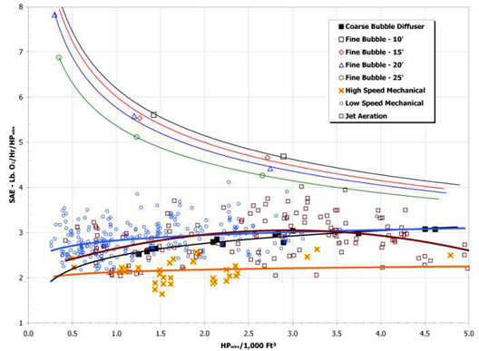
ACTUAL IN-WASTE/FIELD OXYGEN TRANSFER RATES
Rightly or wrongly, AOR/SOR ratios of about 0.7 are frequently used
for quoting or budgeting direct-drive, mechanical surface aerators. However,
until alpha, beta, theta, elevation and required residual D.O. are known the
0.7 factor is nothing but a glorified guess. It should be obvious you don't
want this type of guessing especially in the light of present day
availability of highly qualified treatability assessments.
.
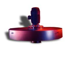
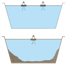 There is a MAJOR difference between a lagoon aerator and an activated sludge aerator. Lagoon aerators are designed to keep the upper aquatic zone aerobic but not necessarily mix the bottom solids. Activated sludge aerators are designed to mix all suspended solids for maximum contact with biomass and oxygen, and keep the bottom of the basin clean -- that is no sludge deposits. Thus, some lagoon type aerators would not work well for activated sludge type applications such as some BNR systems.
Some floating aerators are OK for facultative lagoons but do NOT provide the deep mixing needed for aerobic basins in activated sludge processes.
Fine bubble aeration is acceptable from an AS process point of view but is best suited for rectangular tanks and requires a separate blower building and controls. Fine bubble systems are not good for earthen basins with sloping walls because it is difficult to get good spatial coverage. The floating draft tube aerators are best for earthen basins that are designed for AS applications. Draft tube and fine bubble likely are no different from a volatile emissions point of view since it takes about the same volume of air to meet the oxygen demands.
Oxygen transfer rates in clean water without duly adjusting for actual, in-waste conditions will very likely lead to severe performance issues or even wwtp collapse.
For the purpose of rough calculations we can, whatever the units used, and using say COD as constituent, combine these two formulas:
Yn = Yo * ( 1 + 0.2 * Kd * SRT) / ( 1 + 1.2 * Kd * SRT)
Yn = bugs in tank * 100 / ( SRT * kgCOD/day * COD removal points)
Thus we have
bugs in tank * 100 / ( SRT * kgCOD/day * COD removal points) = Yo * ( 1 + 0.2 * Kd * SRT) / ( 1 + 1.2 * Kd * SRT)
Solving for one of the SRT we get the coveted iteration formula:
SRT = bugs in tank * 100 * ( 1 + 1.2 * Kd * SRT) / ( kgCOD/day * COD removal points * Yo * ( 1 + 0.2 * Kd * SRT) )
From now on it's just a matter of allowing Excel to perform circular reference iterations (you may have to enable this setting in your Excel version).
For those unfamiliar with iterative methods (a numerical analysis classic) one way to find a root of an equation is to solve for the variable and give iterative methods a try.
Were we to find a root for say
a * x^2 + b * x = (a * x + b) * x = 0
One possible iteration formula to try could be solving for x as follows:
x = 1 / (a * x + b)
While it may seem laughable to do it for this case the truth is that it works great for the not so immediate cases. With minor tweaks it can be used for UASBs, HAFs, BVFs, BNR TFs of all sorts.
It is not wise to use air stripping for nitrogen removal. Aerobic nitrification/denitrification is much more economical. Some possible treatment train may be as follows:
1. Anoxic/aerobic nitrification/denitrification in tanks-in-series arrangement (ie. AO2, Bardenpho, UCT, etc.)
2. Alum precipitation in an independent flocculation-clarifier from the aerobic process to remove phosphorus and to precipitate suspended solids (This separate clarifier avoids adding chemicals directly to the aeration system). Some powdered activated carbon may have to be added to remove color and soluble organics if color and additional COD removal is required.
3. Granular media filtration for final suspended solids removal
4. disinfection as needed.