
www.LandfillFundamentals.com
A Primer on Landfills | Fundamentals & Applications


Applications
|
|
|
|||||||||
|
www.LandfillFundamentals.com
|
||||||||||
|
A Primer on Landfills | Fundamentals & Applications |
||||||||||
|
|
|
|
|
|
||||||
| |
||||||||||
|
|
||||||||||
|
|
Applications |
|||||||||
|
SUBSURFACE CONDITIONS
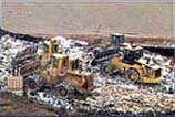
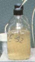
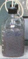
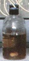
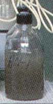
There are several aspects that must be examined as regards underground characteristics of a given potential site. Because of the need for suitable cover and liner material, subsurface soil type characteristics are not to be trifled about. Siting a landfill in the wrong place may translate into having to bring in cover soil from far away places. Soil and subsurface characteristics are important as well because we would tend to look after "spontaneously good" (= naturally impervious) subsurface terrains such as clays or silts. Underground matrices consisting of gravels or sands will not do. Proper soil characteristics can play an important role in migration control. Targeted site location soils will have to be appropriate to provide a firm foundation and construction involved, including roads and minimizing liner damage potentials. Distance to groundwater will determine to a certain extent how deep we can go. Subsurface formations and groundwater conditions will have an impact when designing leachate collection and lining systems. Vertical and horizontal migration patterns may translation into leachate migration to undesirable places. LANDFILL LEACHATE Based on a number of treatability assessments conducted, landfill leachates are very difficult to treat. They contain significant amounts of nonbiodegradable or very slowly biodegradable organics and often contain substantial amounts of color. Heavy metals usually are a minor problem since they will be absorbed by the biomass. Nitrogen levels usually are high so that ammonia released or there will be a demand for oxygen to satisfy nitrification. High O&G probably. It is recommended that treatability tests be conducted so that the designer will know exactly what removal efficiencies can be achieved. BASIC LANDFILL DESIGN PROCESS The complex procedure for designing a given landfill can be divided in about five major design steps. 1. Establishment of goals and design data including determination of solid waste quantities and characteristics, both actual and projected for such things as type of waste to be accepted/rejected; areas to be served; planned life, user profiles; tip fee schedules, population and future growth data, current and projected solid waste generation rates figuring in any commercial/industrial development and assessing effect of recycle and recovery programs. 2 Compilation of information for [the various] potential sites including but not necessarily limited to:
3. Sizing of filling area which will include
4. Specific features such as
5. Package preparation, i.e. plans, diagrams and documents of all sorts such as
|
|
|
|
www.AerationFundamentals.com - www.ExtendedAeration.com - www.OxidationDitches.com - www.TricklingFilters.com |
||
|
www.Biotowers.com - www.MembraneBioreactors.com - www.AnaerobicReactors.com - www.AnaerobicFilters.com |
||
|
www.UASBs.com - www.EGSBs.com - www.CoolingTowerFundamentals.com - www.EvaporativeCondensers.com |
||
|
www.DewateringFundamentals.com - www.BioremediationFundamentals.com - www.IncinerationFundamentals.com |
Join us on: www.Facebook.com/IndustrialWastewater