www.MechanicalAerators.com
A Primer on Mechanical Aerators | Fundamentals & Applications


Fundamentals
|
|
|
||||||||
|
www.MechanicalAerators.com
|
|||||||||
|
A Primer on Mechanical Aerators | Fundamentals & Applications |
|||||||||
|
|
|
|
|
|
|||||
| |
|||||||||
|
|
Fundamentals |
||||||||
|
E-mail us at frontdesk@engineer.com!
|
|||||||||||||||||||||||||||||||||||||||||||||||||||||||||||||||||
|
Broadly speaking, mechanical aeration systems are popularly
classified as either surface aeration systems or submerged
type aeration systems.
Typical examples of surface aeration systems include most frequently floating or pier-anchored mechanical type units, such as direct-drive, high speed units or gear driven, low speed units. Flow can be either upflow or downflow and either axial or radial/centrifugal. A typical direct-drive, high speed unit consists of a motor, a fiberglass or stainless steel float and an intake/suction cone. The most common designs can be marine type impellers assisted with fixed/non-rotating diffusion heads or screw centrifugal, Archimedes type impellers. A good quality, high speed unit can and should deliver say about 2.4 lbs O2/hp/hr, +/-10%, in clean water. A typical gear-driven, low speed unit consists of an electric motor, gearbox, relatively large diameter rotors (say up to 10' or 3.2m), spool and mounting plate for pier-mounted units Floating type low speed units include knocked-down, float platforms that can be easily assembled onsite. A good quality, low speed unit can and should deliver say about 3.5 lbs O2/hp/hr in clean water. . Mechanical surface aerators are typically employed in the relatively shallower ponds, basins or tanks. Evaporative cooling does take place which may be undesirable or unacceptable in some contexts. Volatile organic compound stripping can be significant and/or again unacceptable. As mechanical surface aerators pump up and splash out liquid, they induce very high
velocity flows directly beneath them, and in some instances may cause damage to basin floor. In earthen or lined basins, aerator vendors usually recommend the use of bottom concrete pads directly below the units, although wastewater and concrete/other proposed material compatibility must be verified.
Surface aerators also project sizable horizontal patterns which may unduly impinge on basin walls risking leaking potentials. Riprapping or similar shore structures can protect basin walls. Submerged, turbine-type aeration systems include slow rotating bottom impellers coupled with grade level blowers. The submerged impeller draws liquid from the bottom for reactor mixing and effects oxygen transfer/bubble shearing Blower units provide air to the submerged turbine assemblies, (e.g. 35-40 SCFM per turbine share motor HP, ballpark 50/50 total HP split between blower and submerged turbine) via flexible hoses as needed to satisfy specific operating modes/targets, e.g. just mixing (off) , anoxic stage, SBR phases, filamentous bacteria control. Submerged jet aerators, i.e. basically a grade-level pump and submerged venturi-type diffuser, call for 8 to 10 m deep water levels. In this type of system, mixing and air supply can be operated independently of each other, i.e. pump only or pump and controlled introduction of pressurized air. Aspiration type units provide good oxygen transfer but also cause a circular pattern of flow through the reactor. This circulation pattern is OK if the basin type requires circulation, such as oxidation ditches and facultative lagoons, but BNR reactors do not need this circulation. Aspiration type aeration devices also provide a high velocity jet that can cause erosion of the bottom or sides of the basin if the basin has a shallow depth or the unit is too close to the side of the berm. Most ATAD processes use aspiration type aerators with oxygen transfer rates well above 2.5 lb/HP-hr. In fact, ATAD processes are made possible by the high oxygen transfer rate capabilities of these aerators. Most types and brands are suitable for AS applications, but each has its own best applications. For example, brush aerators are best for oxidation ditches while surface aerators and diffused aeration are best for conventional AS systems. The more challenging industrial applications would probably point to mechanically-based configurations. The industrial reader is referred to say the paper by Dr. J. Musterman. The key is to size the unit properly for each application. Once OTR characteristics are established, the sizing is fairly straightforward. Other factors include alpha factor, impact of floc size and settleability, impact on effluent TSS, etc. The key phrase is "if properly sized/selected."
LOADING RATES For conventional activated sludge of average rate, i.e. medium rate, it is generally recommended approximately 50 lbBOD/1,000 cu.ft. as maximum. For process stability and better assurances of performance, so called low rate aeration systems favor the use of low f/m and that is generally restricted to about 10-15 lbBOD/1,000 cu.ft. This significantly lower rate sizing tip takes into account process recommendations such as extended aeration, BNR regimes and/or other targets. BASIN DESIGN AND TANK DEPTH Design of the aeration
tanks is also important for optimum efficiency. Proper tank design can make it or break it for any given aeration system selection. It is often the case that the same identical piece of equipment or given amount of hardware will deliver far more return for the investment if only careful/generous process considerations are taken into account, adding buffer treatment capacity.
Direct-drive, high speed, mechanical surface aerator sample data.
Coupled with oxygen dispersion and complete mix diameters/data for the
various units the chart would enable working out alternate layouts to
accommodate available geometry/other.
|
Direct-drive floating units
Directional floating unit (layout is critical)
Direct-drive, high speed
Downdraft mechanical aerator
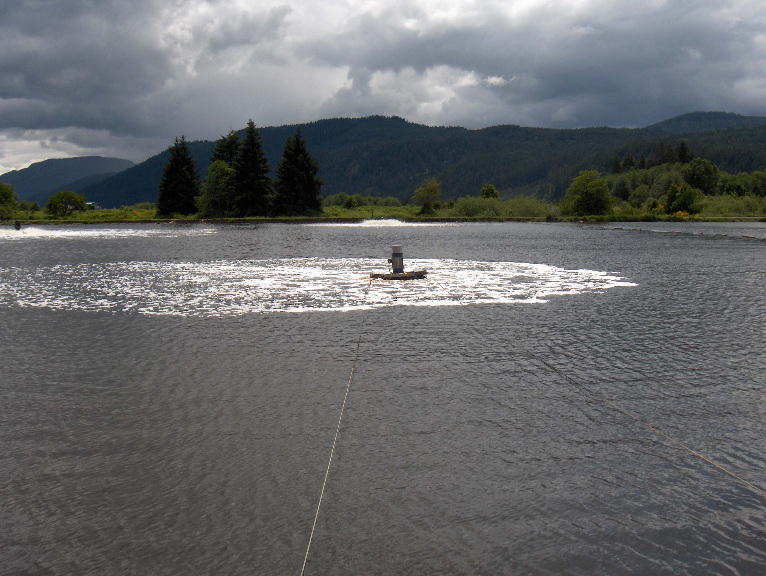
Submerged, turbine type unit (blower not shown)
Large Aerated Lagoon Application |
||||||||||||||||||||||||||||||||||||||||||||||||||||||||||||||||
|
Thomas Irwin, M.S. Environmental Scientist/Rutgers
|
|||||||||||||||||||||||||||||||||||||||||||||||||||||||||||||||||
|
www.AerationFundamentals.com - www.ExtendedAeration.com - www.OxidationDitches.com - www.TricklingFilters.com |
|||||||||||||||||||||||||||||||||||||||||||||||||||||||||||||||||
| www.Biotowers.com - www.MembraneBioreactors.com - www.AnaerobicReactors.com - www.AnaerobicFilters.com | |||||||||||||||||||||||||||||||||||||||||||||||||||||||||||||||||
|
www.UASBs.com - www.EGSBs.com - www.CoolingTowerFundamentals.com - www.EvaporativeCondensers.com |
|||||||||||||||||||||||||||||||||||||||||||||||||||||||||||||||||
|
www.DewateringFundamentals.com - www.BioremediationFundamentals.com - www.IncinerationFundamentals.com |
|||||||||||||||||||||||||||||||||||||||||||||||||||||||||||||||||
Join us on: www.Facebook.com/IndustrialWastewater